lasciate un messaggio
Se siete interessati ai nostri prodotti e desiderate maggiori informazioni, lasciate un messaggio qui; vi risponderemo il prima possibile.
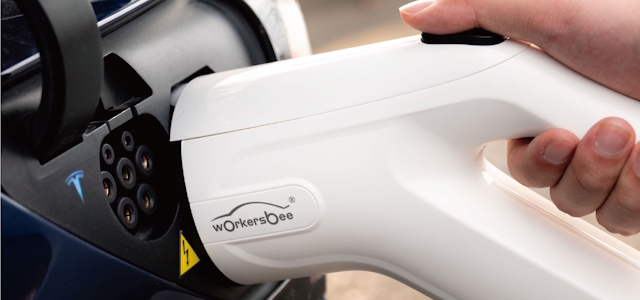
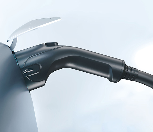
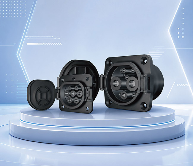
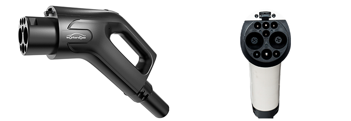
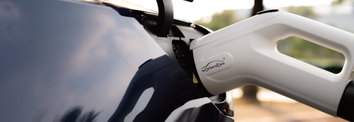
| Tipo di progetto | Direzione del prodotto | Fattori chiave di selezione | Informazioni da preparare |
|---|---|---|---|
| Apparecchiature di ricarica CC a bassa potenza | Connettore CC a bassa potenza G3.0 | 20–80A, 750/1000V CC, dimensioni e gestione del cavo | Corrente e tensione nominali, lunghezza del cavo, terminazione lato caricabatterie |
| Apparecchiature di ricarica rapida CC | Connettore CC G4.0 a raffreddamento naturale o a liquido | Configurazioni di corrente massima da 80–350 A o 400 A/600 A, diametro del cavo, requisiti del sistema di raffreddamento | Profilo di corrente richiesto, tensione, architettura di raffreddamento, lunghezza del cavo, condizioni operative |
| Apparecchiature di ricarica CA | Connettore CA G1.0 | 16A o 32A, monofase o trifase, 250/440V CA | Fase, corrente, tensione, lunghezza del cavo, cablaggio lato caricabatterie |
| Interfaccia CC lato veicolo | Ingresso veicolo CC GB/T | 80–250A, 750/1000V CC, spazio di montaggio e instradamento dei cavi | Classificazione veicolo-piattaforma, disegno di installazione, spazio disponibile, terminazione del cavo |
| Interfaccia CA lato veicolo | Ingresso veicolo CA GB/T | 16A o 32A, monofase o trifase, 250/480V CA | Fase, corrente, tensione, schema di installazione, instradamento dei cavi |
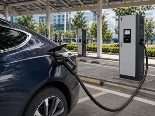
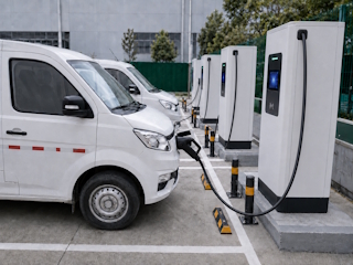
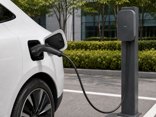
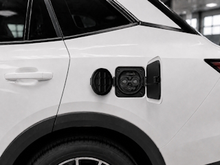


Le attuali specifiche GB/T per connettori e prese per veicoli prevedono un grado di protezione IP55, un intervallo di temperatura di esercizio da -30 °C a +50 °C, prestazioni del materiale dell'alloggiamento UL94 V-0 e una durata meccanica di oltre 10.000 cicli di accoppiamento. Queste specifiche si applicano agli attuali connettori CC G3.0 e G4.0, al connettore CA G1.0 e alla gamma di prese CA/CC per veicoli. Le condizioni di protezione applicabili e la configurazione finale devono comunque essere verificate in base al modello selezionato, al metodo di installazione e all'ambiente operativo.
La configurazione del connettore deve essere compatibile con il profilo di corrente e l'architettura di raffreddamento del caricabatterie. I parametri chiave includono il fluido refrigerante, la portata, la pressione di esercizio, la lunghezza del cavo, la capacità del refrigerante e le connessioni di raffreddamento lato caricabatterie. Il modello G4.0 supporta configurazioni a base di acqua-glicole o olio di silicone, con una portata di riferimento del refrigerante di 1,5–3 L/min e una pressione di circa 3,5–8 bar. I parametri finali del sistema devono essere confermati per la configurazione di corrente massima selezionata di 400 A o 600 A.
Sono disponibili opzioni specifiche per il progetto relative alla lunghezza del cavo e alla lavorazione delle estremità, inclusi i requisiti di terminazione lato caricabatterie. Si prega di fornire la corrente, la tensione, la lunghezza del cavo, le dimensioni di spelatura, i requisiti dei terminali e i dettagli di cablaggio lato caricabatterie richiesti. L'assemblaggio finale del cavo è soggetto a conferma tecnica in base alla configurazione del prodotto selezionata e alle condizioni operative.
Il gruppo di ingresso standard per veicoli comprende l'ingresso, la copertura protettiva, il gruppo cavi, la serratura elettronica e il sensore di temperatura. La lavorazione dell'estremità del cavo viene configurata in base ai requisiti di connessione lato veicolo. Per la conferma del progetto, si prega di fornire la configurazione CA o CC richiesta, la corrente, la tensione, la fase (ove applicabile), la lunghezza del cavo, lo schema di installazione, il percorso del cavo e i requisiti di spelatura o terminazione dell'estremità. L'assemblaggio finale verrà confermato in base alla piattaforma del veicolo e allo schema di installazione.
lasciate un messaggio
Scansione su Wechat :

Scansione su WhatsApp :





 Italiano